Modelling A Linear Array Transducer Example
This example provides a demonstration of using the kWaveArray class to define a linear array transducer with 15 rectangular elements. Electronic focusing is then used to transmit an ultrasound pulse. It builds on the Defining A Source Using An Array Transducer Example.
Contents
Defining the array
The array is defined in the same way as the Defining A Source Using An Array Transducer Example. Here, 15 rectangular elements are added using the addRectElement method of the kWaveArray class. The elements are placed in a line with a fixed element pitch to simulate a linear array. The linear array is then moved by a given translation and rotation using the setArrayPosition method. Note, there is a limitation in the current implementation of kWaveArray for rectangular elements which means the individual elements are not rotated when a global rotation is applied. As a work around, the element angle can be set when calling addRectElement to the same angle as the global array rotation.
% create empty array
karray = kWaveArray('BLITolerance', 0.05, 'UpsamplingRate', 10);

% add rectangular elements facing in the z-direction
for ind = 1:element_num

    % set element y position
    x_pos = 0 - (element_num * element_pitch / 2 - element_pitch / 2) + (ind - 1) * element_pitch;

    % add element (set rotation angle to match the global rotation angle)
    karray.addRectElement([x_pos, 0, kgrid.z_vec(1)], element_width, element_length, rotation);

end

% move the array
karray.setArrayPosition(translation, rotation)
Compared to the kWaveTransducer class (which is used for the Diagnostic Ultrasound Simulation examples), the kWaveArray class is much more flexible. It allows the elements to have any width (not restricted to the grid spacing), the elements to be placed anywhere in 3D space (for example, to simulate curvilinear arrays), and the transducer to be moved to an arbitrary position and orientation. However, kWaveArray doesn't provide methods for calculating beamforming delays, forming scan lines, or setting an elevation focus which are possible when using the kWaveTransducer class.
Generating the source signal
To drive the linear array, a source signal for each physical transducer element is created. In this example, each element is driven using the same tone burst, but with a time delay such that the beam is focused at a given position. The time delays are calculated geometrically using the known element and focus positions.
% set indices for each element
if rem(element_num, 2)
    ids = (1:element_num) - ceil(element_num/2);
else
    ids = (1:element_num) - (element_num + 1)/2;
end

% set time delays for each element to focus at source_focus
time_delays = -(sqrt((ids .* element_pitch).^2 + source_focus.^2) - source_focus) ./ c0;
time_delays = time_delays - min(time_delays);

% create time varying source signals (one for each physical element)
source_sig = source_amp .* toneBurst(1/kgrid.dt, source_f0, source_cycles, 'SignalOffset', round(time_delays / kgrid.dt));
Running the simulation
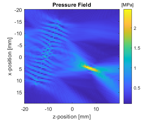
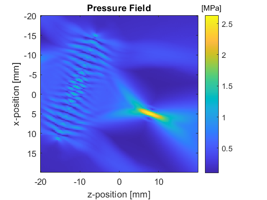
To use the defined array and source signals with kspaceFirstOrder3D, the getArrayBinaryMask and getDistributedSourceSignal methods are used to create source.p_mask and source.p. Plots of the maximum pressure field when running the simulation at 3 PPW and 8 PPW are shown below.

